Installing A/C in an A32 V Berth

WHERE TO PUT IT?

After a lot of thought, the best place for me to install the unit was close to power and water under the port side salon seat.
A hole as large as possible was cut in the top of the seat and the draw and draw facing was removed, after seeing how much space was above the draw, I also cut out the top of the starboard seat and put a shelf in.

The next job was to find a unit that would fit. After a lot of measuring and making cardboard boxes to manufacturers specifications I found the best fit to be the Mermaid 9000 BTU Reverse Cycle.

INSTALLING THE MERMAID 9000BTU REVERSE AIR UNIT

I epoxied (to water proof it) a piece of 3/8” plywood the size of the base of the unit. This was affixed to the liner as close to the water tank bulkhead as possible. A small corner of the liner had to be cut away to allow the board to lay flat.

A transition box was fabricated from plywood. This would allow for a 6” straight through vent (that Mermaid said is required) with a 4” vent off of the side. This Box was fitted to the front of the A/C unit and on the front of this, a 6” round plastic collar was glued to accept the 6” plastic pipe. A 4” aluminium elbow (Home Depot) was attached to the side of the box.

The next job was to cut the holes for the air ducts:

  • 6” hole through the bulkhead in line with the A/C unit into the head cupboard.
  • 6” hole through the front of the cupboard beside the head
  • 4” hole through the bulkhead behind the water tank
  • 4” hole underneath the chart table behind the water tank.
  • 2” hole into the head cupboard to accommodate the wiring harness.
  • 1” hole in the liner to allow for the condensation drain pipe

A hole was cut on the base of the A/C unit by the condensation drain. This was to allow for the condensation drain pipe to be led to the bilge.

The condensation pipe was attached to the A/C unit and the whole assembly was carefully shoe-horned in and screwed down.

INSTALLING THE VENT PIPES

A 6” collar was glued to the back of the hole beside the head and the two 6” collars connected with 6” flexible plastic ducting (Home Depot).

A 4” semi-flexible ducting (Home Depot) was used to connect the 4” elbow to the vent under the chart table.

VENT AND RETURN AIR GRILLS

4” vent grill (marine store)

6” vent grill (Home Depot) the closest size that would cover the 6” hole

Return vent (home Depot) The closest size that covers the area were the draw trim was removed. The only colour available was white so it was sprayed brown.

ELECTRICAL

The control box was mounted in the head cupboard.

The wiring harness was feed through 2” hole and plugged into the control box.

#12 wire was fed from a spare 15-amp breaker that I had on the AC panel and connected to the control box.

The FX-1 thermostat was mounted over the nav station with the wiring being fed back to and plugged into the control box.

WATER INTAKE

I fabricated a manifold for the head intake, it now supplies water to the head, wash down pump and the A/C unit.

As a side bar the wash down pump also supplies water to a sprayer (Home Depot) in the head to wash the head and also the galley to spray the worst off of the dishes before washing to conserve water while at anchor.

The intake line is connected to the 110V pump that is hard-wired to the control box. The water pipe is then led to the A/C unit. All the hoses that I used were 5/8” reinforced PVC. This is over-sized to Mermaid’s requirements, but I wanted to reduce pipe line friction and back pressure because of the underwater discharge.

WATER DISCHARGE

I did not want to discharge through the hull above the water line. I’ve been tied up next to boats running air conditioning at night and it can drive you crazy, so I enlarged the through hull for the sink in the head to a 1 ½” ball valve and connected the A/C discharge to that with a ‘Y’ going to the sink. A ball valve was installed in the sink drain just in case there was any back pressure to push water up into the sink and hence into the boat. As yet there hasn’t been a problem, the only time the valve is closed is if the boat is left for an extended period with the A/C running.

THE MOMENT OF TRUTH

The system was turned on and for 1 ½ hours the whole thing work perfectly, then the coils froze up stopping any air flow. I called the Ontario distributor that sold me the unit. He told me that everything that I had done was wrong and that it was not his problem, that he only sold me the unit and that I would have to deal with the manufacturer. As you can imagine, at this point I wasn’t feeling too good.

I contacted Roger Williams Product manager of Mermaid Mfg. and I can’t say enough about how helpful and positive he was, promising to stay with me until things were resolved.

He reviewed pictures and a description of what I had done and said that basically what I had done was correct. In the end it was determined that the A/C unit was not cycling off to allow the coils to defrost as the thermostat was mounted away from the air flow . The cure was to mount a remote
temperature sensor in front of the coils behind the return grill and connect it to a plug inside the control box.

I’m now in the process of finding ways to distribute the cold dense air throughout the salon and V berth.

The hot air is not a problem as it rises and seems to work better than two 1500 watt heaters.

The head gets so cold that when my wife uses it she turns off the A/C because where the grill is it will freeze your you know what off. I think that I have solved the problem of cooling the V berth. I installed a 3” 12 volt muffin fan in the bulkhead.

The solution for the salon will be to keep the head door closed to force the heavy cold air up over the top.

Plugged into a 15-amp dock outlet, I can run the A/C and boil a kettle at the same time without tripping the breaker.

What were my costs?

Through Hull $49.71
½” ball valve $8.53
Bronze Cap $2.00
Seacock $153.67
Brass Nipples $12.97
Brass Hose Adapter $3.94
Total: $230.82 (this cost is because I wanted to discharge below the water line)


A/C, FX-1, Pump $2403.00
Return Grill $14.40
4” duct $10.16
4” elbow $4.25
4” vent $10.00
Hose & clamps $45.80
Return grill $16.16
Brown Paint $5.29
6” flanges (2) $20.00 $2529.06
Total $2759.88

Note:  some small items may have been missed or donated

Aloha 32 Bilge Drainage Project

Ever since I read “Mortar in the Bilge” by Graham Thomas, I wondered about the aft-most keel-bolt on my A32. From the direction of the bilge hatch, I could see a piece of rusty steel with the nut on top of it, and a few inches behind it, a fiberglass floor timber. When I explored the drainage hole from the engine compartment, I found stagnant water. This puddle of water collected because the drainage hole in the floor timber was clogged, and there was no way of reaching the problem area from either end. I decided to router out an inspection hatch to be able to look at the keel-bolt and to resolve the drainage problem. I made the third floor hatch the size of the other two, so that the two long edges of the new hatch would sit on the stringers.

What an ugly sight it was! This area hasn’t seen daylight since the boat was built. The drainage holes on both sides of the floor timber were the very rough. Oily sludge collected on fallen debris, run away nuts and engine enamel flakes that were caught by fibreglass strands and hard spikes. Only a small amount of  water could seep over the top of this dam. Any spill that happened at an oil filter or diesel filter change ended up floating on top of the “reservoir” behind the blockage. I figure this puddle never had a chance to dry up, so it froze there every winter. In the summer, the floating oil covered the walls of this chamber. On the keel-bolt side, at the exit hole and behind the steel cross piece, there was a hollow area with no drainage. Unfortunately, the exit hole reached down to the bottom of this pit.

After cleaning up the area, I found the steel cross piece in perfect shape. I will get rid of the rust and put some Tremclad on it. I don’t think it would be smart to glass it in. With the drainage problem resolved, and the floor hatch coming off every winter for ventilation, that steel piece should be much happier.

The close up of the hole shows the oily, wet fibreglass mess at the bottom of the tunnel. The hollow inside of the floor timber extends toward the stove area and toward the nav table on the other side. It is impossible to clean it out.

I allowed the tunnel to dry out, and slightly enlarged the holes on both sides to fit a 2″ PVC pipe. With a little epoxy and glass, I sealed the gap around the pipe. Once this seal was done, I started to pour in epoxy to create a new and level bottom that will ensure good drainage. On the stern side, the epoxy has not reached the pipe. I will have to pour in about 200ml of the stuff.

Between the glassed in steel piece and the floor timber the pit is filled in with epoxy. The water will drain on both sides.

The epoxy puddle on the stern side is shallow and goes quite far back. The tunnel pipe is not horizontal, so on the exit side, some epoxy flowed in and leveled the bottom. Just to be on the safe side, I drilled two vent holes into the floor timber. I can seal these later when I know for sure that there is no moisture trapped inside.

The rest is cosmetics. I have to put polyurethane around the new hatch area and then give the entire floor a top coat. Once the stern side epoxy puddle is level with the pipe, I’ll paint the repair area with grey bilge paint.

Written by by Zsolt Kecskemeti

Chain plate replacement

When my wife and I recently purchased a Bristol-appearing Aloha 32, a thorough marine survey revealed that the stainless steel clevis pins used to connect the shrouds had worn the attachment holes in the aluminium chain plates. The survey required immediate replacement of the chain plates and recommended stainless steel as the material of choice.

The old chain plates, easily removed in about 60 minutes a side, had been made from aluminium bar stock. One-half inch thick below decks, they were milled to 3/8 inch thick above decks to accept the yokes for the rigging screws. Each chain plate also included a backing plate

I fabricated six chain plate assemblies for about $150 (Canadian) and about 8 hours work with a hand saw, grind wheel, belt sander, a drill press that was way too small and a Drill Doctor. Materials were purchased at The Metal Supermarket, a franchise chain that sells metal the way an old-fashioned butcher used to sell meat, cut the way you want it.

I used 3/8 inch thick material for the chain plates, together with a 1/16 inch spacer to maintain the original geometry. The old chain plates were used as templates for grinding and drilling.

If you have never worked stainless before, here are some tips: use a GOOD quality hacksaw blade that’s coarse enough (12 teeth per inch for 3/8 stainless) and keep it WELL lubricated with cutting oil, three-in-one oil, or whatever. For drilling, use a slow speed, lots of lubricant and lots of pressure, enough so that the bit is always cutting a good curl. (300-series stainless work hardens very quickly if you smear it around without actually cutting it, becoming impossible in the process.) Most important of all, make sure your drill bits are razor sharp. (This is where the Drill Doctor, a precision drill sharpening tool, comes in. I sharpened my drills after every chain plate.)

This photo shows one complete set (of the six). The new stainless chain plate is at the top, with the stainless spacer in the middle and the aluminium backing plate on the bottom.

If you attempt a similar project on your Aloha 32, note that the dimensions of the uppers and lowers are different.

Enjoy.

Written by Treat Hull

Aloha 32 Rudder Post & Steering Rebuild (2)

When we bought our boat there was up to a 1/4″ play in the rudder post.  After the rudder was dropped (with much effort!) we found the quadrant needed to be replaced as every bolt had to be drilled to be removed.  We found some of the bolts were raw steel through aluminum and stainless steel, corrosion was an issue. An even bigger find was that there were no bearings in the fiberglass rudder tube. The rudder’s stainless steel post was worn at its base, equally worn in the fiberglass rudder tube.

Well here is an update of what we did.  To summarize, the rudder was dropped and the wear inspected and measured.  The quadrant was destroyed and had to be ordered new. The top nylon bushing was in fine shape but the aluminum spacers were fused together and had to be cut apart.

What we elected to do was to build a new bottom bushing out of aluminum and epoxy a nylon sleeve over the damage on the rudder post.  The two new bottom bushings were machined to fit inside each other and provide a new wearing surface for the rudder.Here is what we did:

  1. Measure the diameters of the rudder tube and the rudder stock in two directions for wear, draw up new bushings to be machined, select a machine shop.  I had the bottom bushings done plus the two upper aluminum spacers with the pin and check screw for $230.
  2. Prepare the bottom of the rudder tube for the new bushing.  The diameter of the new bushing will be larger then the existing rudder tube.  We used a hole-saw to increase the tube size.  First run a straight edge down the rudder tube from the cockpit deck to review the angle that the new hole needs to be drilled.  Cut a tapered plug from plywood and insert in the existing tube to help guide the hole saw at first.  Two people will need to guide the drill in order to keep the correct angle.
  3. Clean the rudder stock and sweat the nylon bushing down the rudder stock to the damage. Apply the epoxy over the damage and continue sliding the nylon bushing down to its final position.
  4. Dry run the fit. (We had to assemble the rudder 5 times before it was right). Insert the new aluminum bushing, friction should hold it in place. Next insert the rudder. We used a 2×8 as a lever once the two of us got it in place.  This allows one person to guide it in on top.  Check alignment and fit. Sand as needed. I wanted it to ride with the least amount of effort, but not be loose.
  5. Once happy with the fit we screwed the aluminum bushing in place and inserted the rudder for the final time and then assembled the quadrant.

Some extra notes:

  • You have to dig a 1.5 foot hole under the rudder to let it drop.
  • I removed the wood bulkheads into the space under the cockpit to allow more working space.  We also removed the fuel tank for cleaning, but that’s another project.
  • The rudder was full of water which I drained and then patched the crack at the top of the rudder.

Written by Chris Davison

Aloha 32 Rudder Post & Steering Rebuild (1)

We’ve just finished a complete rebuild of the steering system on our Aloha 32.  When we purchased the boat in November 2005, we noticed about 1/8″ play in the top rudder bearing.  After hauling the boat, we also noticed about 1/16″ play in the bottom bearing.

Upon pulling the engine for repair, we found about 1/2 gallon of sandy sludge on top of the quadrant, on the hull around the rudder post, under the fuel tank and engine, and on down into the bilge.

We disassembled the steering system to investigate.  I’ll describe the construction of the steering system in detail, because I think it will help in discussing the problems and the solutions we chose:

As built, the rudder shaft is a 1 7/8″ OD stainless tube.  Near the top of the shaft is a 1/2″ diameter stainless pin inserted through the diameter of the shaft. Under this are two 4″ diameter, 1/2″ thick aluminum disks.  The 1/2″ rod is secured to the upper disk with a stainless machine screw.  The lower disk rides on a plastic bushing which looks a bit like an inverted top hat.

A 1″ deep drain well extends across the width of the cockpit sole with drains in the outboard corners.  The “brim” of the rudder bushing rests on the floor of this well at the center, with the tubular part extending down through a hole in the floor of the drain well.  The “brim” of the bushing is secured to the drain well floor with three 1/2″ flat-head wood screws.

We found that the bushing, and thus the entire shaft assembly, was moving laterally at least 1/8″ inch when under load.  The bushing was also rotating about +/- 10 degrees when the rudder shaft rotated.  The screw holes were elongated, so the screws were no longer doing their job, and in fact their heads were gouging out the bottom of the lower aluminum disk.

It’s clear that the sand and grit, carried by water from the cockpit sole, migrated underneath the bushing, onto the quadrant, and thus down into the bilge.  In fact, the sand underneath the rotating bushing milled down through the fiberglass into the plywood.

Our lower rudder bearing is a simple fiberglass tube.  Over the 22 years since our boat was built, the rudder shaft was worn down about .003″ in diameter (as compared to the unworn parts of the shaft).  The tube was about .060″ larger in diameter than the shaft.

Unlike some other sailboats, there is no packing gland at the top of the rudder tube.  The top of the tube appears to be somewhere between 3″ to 5″ above the static water line, so when the boat was new, the close fit between the tube and the rudder shaft presumably kept the water out, even when under way.

It’s interesting to note that another Aloha 32 owner recently reported leaking from the front of his rudder tube at high propeller speeds.  We only had a few hours on our boat before we hauled it for refitting, so we didn’t observe any leaking.  (But with the mess in the aft space of our boat, it  might have been difficult to see in any case.)

The quadrant on our Aloha 32 is actually a complete wheel, and is clamped with several bolts, and secured from rotating with a pinning bolt through the shaft.  When we removed the quadrant (luckily it was easier for us than for you), we found the bottom of the quadrant severely eroded, to the point where the pinning bolt was exposed over most of its length.  The rim was also quite rough from corrosion.

Since the quadrant was mounted only about 1/8″ above the top of the rudder tube, one imagines that water splashed up the rudder tube onto the bottom of the quadrant from time to time.  The quadrant, being aluminum and anodic with respect to the stainless shaft, eroded away.

Here’s what we did to solve the various problems:

Bottom Bearing

After considerable research, we decided to rebuild the bearing surface by injecting graphite-loaded epoxy into the rudder tube, using the rudder stock as a mold.  This method is described in section 8.4 of “Fiberglass Boat Repair & Maintenance”, published by West System Inc.

In short, the technique is to remove the rudder, drill several holes into the rudder tube, reinsert the rudder, then use a syringe to pump graphite-loaded epoxy through the holes into the gap between the rudder stock and the rudder tube.

To begin, we dropped the rudder and cleaned up the shaft with coarse emery paper.  We especially concentrated on working down the unworn parts of the shaft to try to eliminate the .003″ step worn by the rudder tube.  We were concerned that since the new bearing diameter would be based on the lower, worn part of the shaft, the upper, unworn part of the shaft might not fit through the bearing when we needed to remove and reinsert the rudder.

Next, we drilled four holes in the skeg from outside the hull, diagonal to the boat’s centerline, and parallel with the waterline.  We originally hoped to find solid fiberglass here, but we found an air gap between the skeg and the rudder tube.  While it might be possible to fill this gap with a low-viscosity epoxy, we decided to simply find a syringe with a longer nose. We ended up drilling 1/4″ holes right through the rudder tube, and 3/8″ clearance holes in the skeg to provide clearance for the syringe nose.

We then applied two coats of mold-release wax to the rudder stock and inserted the stock into the rudder tube, blocking the shaft so it was approximately centered in the tube.

Following the instructions in the West System book, we created a 50/50 mixture of graphite powder and colloidal silica.  (The graphite power adds strength, hardness, and lubrication to the completed bearing surface; the colloidal silica is a thickening agent.)  We added this mixture to some  System Three epoxy to get a mayonnaise consistency, and loaded the result into a syringe.

The West System instructions suggest injecting only enough epoxy to form 1″ diameter pads inside the rudder tube.  We instead injected enough epoxy to form a 2″ to 4″ band all around the tube, since we wanted to form a barrier to water coming up the tube.  Using a bit of simple geometry, we determined that 20 ml should be about right, so we injected about 5 to 7 ml into each of the four holes.

It’s important that the syringe fit tightly into the hole in the rudder tube, since you need to apply significant pressure to get the epoxy to flow inside the tube.  We had one hole that didn’t fit well, so the epoxy squeezed out past the syringe.  The resulting bearing surface at that point was only about 2″ high, rather than the 4″ of the rest of the bearing.  Next time, I’d epoxy the bad hole and re-drill to get a better fit before injecting.

While injecting, we could tell that the epoxy was flowing as desired, and that our calculations were correct, because we could see the epoxy show up at the holes on either side of the first holes we injected into.

We let the epoxy cure for about eight hours, then turned the rudder to break it free, and then came back every few hours to break it free again.  We left the rudder in position for about a week to ensure the epoxy was completely set.  We wanted to avoid damaging the new bearing surface when we dropped the rudder for the rest of the required repairs.

Top Bearing

While the bottom bearing was curing, we set to work on the top bearing. Since we had hammered pretty hard on the top of the rudder shaft to get the aluminum disks off, the floor of the drain well, which was already damaged by the sand milling away the fiberglass, was now delaminated as well.  To begin the repair, we ground away the loose fiberglass and wet wood over an area about 8″ square.  We then used System Three RotFix (a penetrating epoxy) to stabilize the wood and secure the remaining fiberglass to the wood.  Finally, we laminated back up to the original thickness with epoxy and glass cloth.

We wanted to make sure that any water and grit in the drain well would drain away from the rudder bearing in the future, so we added a 1/2″ thick plywood land under the rudder bearing, beveling the edges and glassing it over.  On reassembly, we omitted one of the two 1/2″ thick aluminum disks to maintain the original rudder shaft height.

We eliminated the possibility of water in the plywood by drilling the hole for the bushing about 1/4″ oversize, which allowed space to pack in epoxy loaded with milled fiber around the bushing.

To ensure a really accurate fit of the epoxy around the bushing, we used the bushing itself as a mold.  We first applied a generous coat of mold-release wax to the bushing, then we dropped the rudder a few inches, inverted the bushing and put it on the shaft.  We raised the rudder back into position, pushed the bushing up until it met the bottom of the drain well, and secured
it there with duct tape.  It was then possible to pack in the epoxy and milled fiber around the bushing.  We let the epoxy cure well, then removed the bushing.

Once the hole was cleaned out and the bushing reinserted from the top, it was perfectly aligned with the shaft and had absolutely no slop whatsoever. Finally, we drilled for the bushing retaining screws.  Again, we avoided any future water ingress by drilling a bit oversized, packing the holes with epoxy and milled fiber, and re-drilling for the screws after the epoxy cured.

Quadrant

Even though the rebuilt bottom bearing should exclude water for some years, we wanted to avoid having to replace the quadrant ever again.

The Edson radial drive wheel used on the Aloha 32 is shaped like a shallow dish, with a hub on the bottom of the dish.  As built, the wheel is mounted dish up, with the hub below.  After much careful measuring, we determined that there is enough vertical space below the drain well to mount the quadrant upside-down.  The inverted position puts the hub above, with the
dish facing down.

According to the Edson manual, this mounting arrangement is completely acceptable, as long as the cable runs true onto the rim of the wheel. Mounted in this way, the quadrant is several inches above the top of the rudder tube, so that any small amount of water which may intrude will not be able to reach it.  Another advantage is that the quadrant clamping bolts are now on the top, so are easily accessible from the lazarette for the next time we need to drop the rudder.

Final Assembly

When reassembling the steering system, we lubricated both the upper and lower shaft bearings, the idler bearings, and the steering wheel bearings with Teflon grease.  On the advice of our mechanic, we also lubricated all bolts and the quadrant-to-shaft interface with the same grease, to help  avoid avoid them seizing in the future.

With a new cable assembly, a complete re-bedding of the steering column, and a bit of paint, we figure that with a little luck we’re now ready for another twenty years!

Written by David Querbach

Aloha 32 – The full “Mortar in the bilge” story!

We purchased an Aloha 32 late in the fall of 2001 and during the process of cleaning her up to get ready for launch the following spring we made an unpleasant discovery.  Our purchase survey suggested replacing the aft most keel bolt nut and adding a substantial backing plate.  When I got to cleaning things up and preparing for the job I discovered that Ouyang Boatworks had filled the aft most compartment of the bilge with cement based mortar.  In the mortar was bedded an oak 2 x 4 x 8″ long through which the aft most keel bolt projected.  Most of the mortar and all the oak were then glassed in leaving an arrangement that probably looked proper when new but in the long run didn’t seem to drain very well. It seems this arrangement was chosen because the aft most keel bolt is in too narrow a portion of the bilge to allow a nut (or even a washer) to be run down to the bilge floor.  The builder chose instead to use mortar to build the bilge floor up to a workable level.

The photos below outline the repair steps undertaken. Since these were completed, I’ve been corresponding with a few Aloha 32 owners and it seems there are a number of keel configurations on the water.  One of the people I corresponded with doesn’t know his arrangement because his bilge covers don’t go back as far as mine.  Another had a carbon steel 2″x4″ hollow structural steel piece wedged in the turn of the bilge.  It rusted away so he replaced it with solid steel.  Yet another owner has the keel bolt far enough forward that it can sit on the bilge floor as do the rest.  So there are a number of arrangements.  If you have mine, I hope this write up helps you when it comes time to clean things up.

When we started this “backing plate” project, we found half the glass over the oak had delaminated from the hull. This photo shows the arrangement reconstructed after having initially been disassembled for inspection.  In the photo it is evident that I had already started scratching away the mortar.

The oak board uncovered. When the delaminated glass was pulled off, the oak was messy but still basically sound.  The mortar under the oak was decomposing into sand; quite a mess.  Nevertheless, the oak was still bearing the load transferring it directly to the turn of the bilge.  Some prodding revealed that the mortar was breaking down to a sandstone form (easy to crumble) wherever it was against fiberglass.

The mortar with the very beginning of the excavations in progress. I used a 3/4 “ hammer drill to make swiss cheese of the mortar and then dug it all out.

The bilge cleaned out.  It is interesting to note that the lower half of the bulkhead that contained the mortar was rotted out and the mortar at its base was decomposing into sand and contaminating the rest of the bilge.

The next step was to glass in a new bulkhead well aft in the excavated compartment.  Into this new, smaller compartment was poured about a litre in 4 lifts of epoxy resin filled with chopped glass.  Over the fill were laid about 8 layers of roving and cloth as bedding for the recommended stainless plate.  Everything was arranged, with the help of poured resin, to ensure a clean drainage path from the aft end to the newly opened bilge.

The final arrangement with the new bulkhead in place and the space filled with epoxy and chopped glass. In the end, the plate was icing on the cake because all the other keel bolt nuts bear directly on the fiberglass through a washer.  In this case there is the stainless plate and two washers.  Notice the floor has been re-sanded in this one and has the first coat of varnish.  Another 2 coats, and light sanding has made it look pretty good.

Written by Zsolt Kecskemeti

A32 Fuel Tank “Removal” & Cleaning Project

I was having trouble with my engine quitting on me after several hours of operation in rough seas – the exact time you don’t want to have to think about engine failure. This first happened to me while crossing from Wilson to Toronto on a rough afternoon, taking 20 knot winds over the bow. I was running fine for about 3 hours and then came the dreaded RPM drop we all hate to hear. I thought it would be my primary fuel filter and would make a quick change underway and be done with it. That was not the case. I removed the filter to find it was quite clean. I was finally able to make it to Ashbridges Bay and was towed in by a fellow yacht club member. After enjoying the evening there I was able to start the engine and run it for 6 hours back to Wilson on a calm afternoon day. My thinking is this: When the fuel in the tank becomes disturbed or unsettled the intake from the fuel tank must become clogged. I am guessing that the clog would occur where the fuel intake line makes the 90 degree turn to be pumped to the electric fuel pump. It becomes narrow there and after settling down for a couple of hours it must clear itself.

Removing the fuel was quite easy. I only had half a tank to begin with and I used my oil changing pump to remove all  the fuel. Just as I suspected there was large hunks of “stuff” floating in the tank. There was not a lot of gunk adhered to the walls of the tank, but rather this free floating debris. I also noted in the 90 degree angle from  the tank to the electric fuel pump that the ball valve was full of debris. I also pulled out a piece of silicon that was used during installation that was caught in this position.

Once the tank dried out I placed my shop vac on blow and stuck the hose in the inlet. I was afraid of fumes while I was cutting. So as a precaution I ran the blower on my shop vac while I was cutting. I cut a 6″ hole in the top of the tank and this allowed me to reach in and wipe the tank clean with acetone. I used a small amount on a rag just to pick up loose debris that was not siphoned out. I also was very thorough to ensure I did not leave any metal shavings from my jigsaw in the tank. It worked quite well.

After cleaning I secured the flange with the rubber gasket (it’s not actually rubber, but I had a hard time finding something that could handle contact with diesel fuel. If anyone needs any of this material let me know. I had to by a square yard and only used and 8″ square piece.) I secured it to the tank by using self-tapping sheet meal screws. I pre-screwed the holes so I was able to clean up any metal shavings before my access was gone.

The true test will come when I have the tank filled and heel the boat over to check for leaks. I feel confident that the gasket material and the dozen screws will provide the necessary and appropriate seal, although I will certainly verify it visually.

I wanted to have my fuel tank steam cleaned. My original plan was was to simply remove the tank through the sail locker, but the opening was about 3/4″ to narrow.  The “traditional” design Aloha 32’s do not have this locker and I have no idea how I would have done this job in that situation. I believe the only way to get to the fuel tank on the other designs is to remove the engine. I plan on doing this job on CELEBRATION (A32 – #58).

Written by Bill Fleming

Aloha 32 – Shaft Replacement

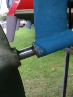
I have been working on replacing my prop shaft after I bent it by wrapping a sheet around it on the very last sail of the season last year. Actually, I am embarrassed to say it wasn’t even a sheet but rather a dock line because I was lazy and was sailing alone. When I sail alone I will often take my spring line with me so when I come in to my slip I can get off the boat with the spring line in hand. Well, while I was sailing and the engine was off, the line wrapped and needless to say I could not get the engine in gear. I had a “great” idea to try to put it in reverse to see if I could unwrap the line – forget about it. I did not think I would have done as much damage as I did because the shaft was not turning and suddenly come to a complete halt as the line jammed. I was wrong. There was enough torque to cause the 1″ shaft to bend ever so slightly and make my engine wobble and vibrate. So I thought it would be a good idea to remove and replace the shaft and cutlass bearing on board Valkyrie. I learned quite a bit and thought I would pass on some of my thoughts to those who may have to do the same thing some day.

My original thought was I would have to drop the rudder in order to get the shaft out. I was dreading that job and thought it would be much easier to pull the shaft into the boat. Obviously, a much better and easier way to complete the mission.

In order to remove the shaft and pull it into the boat I had to remove the coupler from the prop shaft by removing the two bolts that screw into the shaft at 90 degree angle. Once those were removed I was able to remove the key way. The shaft was now free from the coupler, however it was a tight fit and I had to remove the entire couple from the transmission by removing the four bolts shown.

I loosened the stuffing box nut and simply pulled the shaft into the boat, after of course the prop was removed which I needed a prop puller to accomplish.

I had researched how to get the cutlass bearing out and was told to press it out using a threaded rod with bolts and washers. I opted to cut it with a hack saw blade. It took about a half hour and I was very careful not to cut into the strut. Once I had a cut in the bearing it was easy to tap out. Remember there are two set screws (not shown) holding the bearing in place. The replacement bearing I needed was called the “blackfish” and was ordered through West Marine at a cost of about $45.00 (US). I did not realize, until I had the new bearing in my hand, how worn the old one was. The wear was significant.

I then had my shaft duplicated at the local machine shop at a cost of about US$250.00. I replaced the anode and repacked the stuffing box using Teflon packing.

Now the tough part – Aligning the engine with the prop shaft. The shaft was reinstalled and the prop was secured. Without attaching the coupler I could see the prop shaft did not align perfectly to the center of the transmission opening where the coupler attaches. When I installed the shaft to the coupler and the coupler to the transmission the shaft had an elliptical motion. This motion caused undue wear and stress, especially to the stuffing box. It also added unwanted vibration. I spent two days tweaking the engine mounts to MOVE THE ENGINE TO MEET THE SHAFT. I still have an extremely minor “wobble” that I can’t get rid of. I felt that this is the best I could do, and compared to other engines I looked at, mine was “true” enough. The most important thing I learned; the four bolts on the outside circumference of the large coupler ARE NOT ADJUSTMENT BOLTS. They are simply bolts attaching the two round couplers together with rubber bushings to dampen vibration. I had someone else look at the elliptical pattern I could not get rid of and they adjusted these bolts, only later to discover they are not to be touched. Bottom line, I had to go to my machinist again to have the unit put back together because I could not get all the bushings back in line. That cost me a day! One more point. I was checking my transmission fluid level and discovered my dip stick, which should be attached to the filler cap as one unit, separated and the metal dip stick fell into the transmission! Fortunately I was able to get it out, but I lucky to find it before it was ground into the gears and cause major problems with the transmission. Oh, by the way, replacement cost is (I hope you’re sitting down) $112.00 (US). I decided to either epoxy or solder mine back together! This is a brief overview and I could go into more detail, however I think it gives pretty good idea of the project.

Written by Bill Fleming